Comprehensive Safety Diagnosis
-
The lower part of the bridge pier, check
Underwater check (check in depth of water)
Subsurface exploration, Soil test
Foundation loading test
Rock strength test
-
Appearance investigation
Foundation scour, deformation check
Crack check, traffic flaw volume check
Concrete falling and scaling check
Steel corrosion and deformation check
Steel painting and condition check
Deflection check, Road condition check
Incidental institution condition check
Profile leveling, Environments check
-
Quality test of the concrete
Repulsion hardness test
Ultrasonic test (Elasticity by low frequency, density, Poisson's ratio)
Steel reinforcing condition check (arrangement of the bar, the distance across, corrosion condition,)
Neutralization test
Compressive strength test
Salt quantity test
Tension strength test of the steel reinforcing
Mixed proportion analysis
Chemical analysis test
Concrete adhesion test
-
Quality test of the Steel
Steel thickness survey
Examination of method condition (dry film thickness, pin hole test, test of adhesive power of paint. etc)
Inspection of welding defects → R.T, M.T, U.T, P.T, V.T
Hardness test
Tension strength test
Inspection of metal construction
Fatigue test
-
Examination of load carrying capacity (reference of load test method)
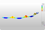
Deformation ratio of the steel structure survey : strain gauge (FLA-5-11-IL(5㎜))
Deflection survey : displacement transducer (CDD-100(10㎜))
Deformation ratio, deflection, acceleration survey : data logger (MT-16)
Data analysis and record : software (STA : strain & test analysis)
Acceleration survey : accelerometer with built-in- electronics (393C(±2.5G))
Slope survey : accelerometer (KB-10E(10Deg)
Amplifier : signal conditioner (480A22(4CH))
-
Total analysis of the measurement result
Structure analysis
Comparison with the measured value of the static·dynamic response and calculated value
Grasping of vibration moving, examination about the possibility of using
Quality condition durability decision
-
Comprehensive report preparation
Load carrying capacity valuation
Presentation of the complement·reinforcement plan
Determination of reconstruction
-
Outline
The loading test plays a very important part in structure analysis and safety valuation of bridges.
We measure deflection and strain that are caused by the static load of each member, and then compare the measure with the theory and we test a static loading ability that to recognize the actual load carrying capacity of bridges and measure the stress and experience of displacement that occur in bridges when vehicles pass there. We must test a dynamical loading ability at the same time to grip a degree of impact produced when vehicles pass there and dynamical traits of bridges. Currently, MISUNG can use WIDAS (Patent No.: 10-1121215) to wirelessly obtain data from the result of the load test without noise through a laptop computer. WIDAS consists of a main controller and a client, and by connecting various sensors to the client, unmanned remote real-time monitoring and structural loading test are possible. -
Loading vehicles for test
Loading vehicles for test must be than 60% of designed maximum passing vehicles + total passing live load of bridges hat have the first grade load age.
The example of a loading vehicle for test if the bridge that passing load is 43ton (the first grade, vehicle's load + load age)
-
Selection of a test span
It is a rule to select the one weakest span considering of bridge seat, expansion joint, damage of the main beam and repair records, but that is possible to increase the place of test span as a lengthening of the whole bridge.
In case that the upper structure is composed of two or more forms, or the association continuous bridge with simple one, it is made a rule to select a span in each form and enforce the loading test. But in case that it is possible to divide into a part of forms except main one or in case of no necessity of loading test clearly when considering damage, state of worn-out, substructure condition, the composition ratio and reinforcing power, it is made an exception of this process.
The loading test for the special purpose of the identification and partial span is made an exception of that.
The loading location is set up in places that support the heaviest load (middle of bridge) or at the most dangerous member.
-
Attachment of the measuring instrument and sensor
The kinds of test, sensor and measuring instrument as well as attaching place, quantity, load and test frequency is determined as the design load, the whole lengthening, span length, upper structure style bridge width and test purpose of this bridge.
The measuring instrument and sensor is attached in order to measure the compression, tension, bending strain, shearing strain, maximum deflection, vibration, dynamic feature and crack behavior.
The quantity of the measuring instrument and sensor is enforced as spot in previous stated blueprint and in case of slab-bridge, it is made a rule to attach the measuring instrument and sensor against the overall width and separate from as far as the distance between spindles of testing truck, and in case of special bridge or box-bridge, determining fit for the test purpose.
The continuous bridge is set up with the measuring instrument and sensor in the moment and side, considering the extent of load effect.
In case of attaching sensor on the upper slab, the separate damp proofing and protecting process is demanded for fear of damage and interference by the direct ray of light, moisture and foreign substance.
We have to be able to compare each measurement result mutually with the measuring instrument and sensor attached a point in a pair.
-
The loading weight selection
The loading weight is measured by the dump truck carried with earth and sand in extend that the axal load ratio don't depart from regulation largely of a front 1 back wheel within 60 percent of load of bridge plan. But the case that additional damage is concerned with the loading test because of serious worn-out and damage makes an exception of it.
The dump truck for loading test must be selected the highly efficient one, and in case of two-lane bridge, one truck is loaded and four-lane bridge, two trucks. And in case of the latter, the total load gap between trucks must be within ± 5 percent.
-
The loading test plan
The loading test period should be decided the hour traffic control little affected in considering of the economical and social damage such as the condition around bridge vehicle quantity and security of pedestrian.
In case that it's rainy or the temperature is over the operating extent of the measurement gauge the loading test doesn't operate.
Concrete bridge in case of the concrete bridge, the loading test isn't executed before 56 days.(age)
The initial loading test is taken before starting vehicle control and the result is kept, recorded and should be compared with the measurement result about the behaviour of bridge in advance.
-
The security plan
The person who takes the loading test and controls the traffic should wear the clothes all to be visible at day and night.
We establish and run the sign board used for several traffic control, emergency light and assistant device.
After ending the loading test, the surface of bridge damaged partly must be recovered.
-
Static loading test
As the term of common use is prolonged, soundness deteriorates in the initial behaviour predicted under planning process of bridge caused by decline of material durability and structural worn-out. Therefore we survey the deflection and the strain of each member by static loading weigh and analyze the actual behaviour of bridge on test, and then compare the actual survey value with the analysis value by the theory and we can get the actual load carrying capacity of bridge. The static loading test decides the measuring place, loading place of vehicle for test and measures the static deflection and static strain according to followings.
decision of neutral axis place
Horizontal division of load
Compounding interaction between main girder and floor deck
Stiffness of member
Influence line of stress and deflection
Comparison the calculated stress with measured stress
Analysis about the behavior marked at the measuring sensor
- 1-1) The load test is taken in state of suspension the common vehicles except loading ones completely.
- 1-2) We establish the initial value of each loading case in state of not loading the live load including loading vehicle.
- 1-3) After loading the tested vehicle, all factors that may affect measurement result such as the vibration, noise, impact of upper structure are removed, and then begins to measure.
- 1-4) We make it a rule to measure three or more times repeatedly in each loading case.
- 1-5) In case of four or more-lane bridge, we establish the initial value in each loading case and then divide into loading a vehicle, loading two vehicles towards bridge width at the same time and measure.
Testing method
- The measuring place of static deflection is decided depending on the size of tested bridge and the aim of load test. We must set up the measuring point in the middle of each main girder and add the number of measuring point such as 1/4 point, 3/4 point of span at need.
The static deflection
- The measuring place of static strain is decided so that we can apprehend the section force in member and stress distribution from the measuring result.
- 3-1) We attach the strain gauge to the upper, lower section of the simple bridge that maximum of bending moment happens.
- 3-2) We attach the strain gauge to the upper, lower, middle of the continuous bridge that the original maximum and side of bending moment happens.
- 3-3) We attach the rosettes gauge in order to measure the shearing strain of main girder part.
- 3-4) In case of compounding main girder, we attach the strain gauge to the upper flange of section that contacts with this in order to examine the compounding behavior of concrete floor deck and main girder.
The static strain
-
The dynamic loading test
The dynamic load test of the bridge is divided largely into two parts. There is the test for impact coefficient and vibration valuation of the actual bridge from the dynamic correspond as the tested vehicle running
- 1-1) The dynamic loading test is executed in state of suspension the common vehicles except loaded ones excluding the special aim.
- 1-2) In case that the measuring instrument for static load test is different from the one for dynamic load test, we use dynamic loading test for the measuring and choose the some of loading case as that of static load test and test of the static loading test in order to examine the error of the measuring instrument.
- 1-3) The velocity of tested vehicle is minimum 5km/h to planning maximum velocity, but the case that alignment of approach road, road condition, condition of suspension vehicles isn't allowed make on exception of it.
- 1-4) We take the driving test of same velocity both in up and down line classified by driving velocity.
- 1-5) Using the result of measurement, we analyze the dynamic properties of bridge such as impact coefficient dynamic strain, acceleration, natural vibration frequency and vibration period.
Driving test
- 2-1) That is the test for the dynamic property of bridge, that is, natural vibration frequency, attenuation decay ratio, mode and also the test that is measured common weak vibration, the behavior of driving vehicle, the vibration by the applying instrument with accelerometer and displacement seismograph.
- 2-2) In case of long bridge, the dynamic property of tested bridge in valuation of earthquake-proof refuge, wind-proof refuge is used as the basic data and the difference of dynamic property as the term pasts at the common using bridge is used in valuation of damage.
Test of dynamic property
-
Loading location and travel velocity
loading location : 1/2 span
No. Method Velocity Remark 1 no-loading 2 static loading 3 dynamic loading 10 km/h 4 dynamic loading 30 km/h 5 dynamic loading 60 km/h 6 dynamic loading 40 km/h dynamic loading 7 dynamic loading 80 km/h -
Valuation of load carrying capacity
- Main measuring items and method establishing the measuring sensor
- The static strain : The method, the attaching place of strain gauge by forms of each bridge and measuring time that is used on test of load carrying capacity, is decided from compute simulation in laboratory and existing data.
- The static deflection : In case of long the bridge at the valuation of static load carrying capacity, we try to find the method that makes dial gauge for measuring the static deflection attached easily or substitution by data and actual test.
Method of static load carrying capacity valuation
- Main measuring items and method establishing measuring sensor
- The acceleration : We decide the measuring material, method and place for measuring the acceleration useful in test of load carrying capacity through the existing data and computer simulation analysis.
- The dynamic strain : We measure the dynamic strain and compare it with acceleration and dynamic displacement. According to that, we apprehend the usefulness about the test of load carrying capacity of dynamic strain and use it.
- The dynamic displacement : Among the dynamic properties of structure, we measure the representation dynamic displacement and examine its usefulness, then compare with the acceleration and the dynamic strain or investigate about the allowed value.
The method of dynamic load carrying capacity valuation
-
Valuation of load carrying capacity
We analyze the structure by the several kinds of structural analysis programs or the finite element modeling in order to valuate the basic load carrying capacity about tested bridge. In the structure analysis, we calculate the stress and deflection of each member followed the load if dead-load, two kinds of testing load and planning load, and presume the common using load carrying capacity on basis of basic load carrying capacity.


-
The exterior check of the outside tunnel
Safety of retaining wall and entrance structure
Check of surface and soil at upper part of tunnel
Check of the tree condition
Fluctuation in contiguity facilities of the tunnel, decision of collapse or not
Laying things institution check
Inspection of feed canal, drainage canal
-
Appearance investigation of inside tunnel
Differential settlement of the tunnel ground
Crack, concrete falling, scaling, spalling, reinforcement corrosion, deformation, displacement
Leakage
Surface deterioration check (damage of efflorescence, scaling. etc)
Road condition, incidental facilities condition check
Concrete thickness and crack depth check
Check the void in the back of the concrete
MIMP 15 (impact elastic waves test)
Profile, cross leveling
Environments check (lighting, ventilation. etc)
Traffic flaw volume check (harmful gas, subsurface water pollution. etc)
Vibration and noise check
-
Quality test concrete
Repulsion hardness test
Ultrasonic test
Reinforcement arrangement condition and corrosion condition check
Neutralization test
Compressive strength test
Salt quantity test
Elastic modulus survey
Mix proportion analysis
Absorption ratio check
Concrete heat of hydration
Time survey (dependence on ASTM-C-1074)
-
Examination of the earth's surface, the nature of soil and the ground
Surface, Geological survey
The ground exploration (G.P.R)
Pile load test
Rock physical test
Rock permeability test
Soil test
Impedance test
-
Total analysis of the field measurement result
Cause damage analysis
Structure safety (structure analysis) valuation
Usability review
Quality condition, durability decision